Both the angle adjustment mechanism and the height adjustment mechanism have brass pins. Starting with 3/8" brass rod, I cut to length the rods and filed the ends square.
Then I chucked them into my drill press, (with the drill running at a low rpm) sanded them up to 400 grit, and cut a chamfer on the bottom edge.
Using the edge of a small triangular file I cut notches, finishing with the edge of a flat file (I think the 90 degree angle looks better than the 60 degree).
I then polished the rod by holding my buffing wheel up to it (with the drill on). They turned out pretty well. Not bad for not having a lathe!
Showing posts with label Hands-on. Show all posts
Monday, June 4, 2012
Sunday, June 3, 2012
Stand Lip
Gluing the walnut lip to the stand:
After the glue is dry I will plane the cherry flush with the walnut.
With this done the only remaining things to do on the stand are screwing the stand on to the post, finishing the stand, drilling the holes for the adjustment mechanism, and making the pin for the height adjustment mechanism. So close!
After the glue is dry I will plane the cherry flush with the walnut.
With this done the only remaining things to do on the stand are screwing the stand on to the post, finishing the stand, drilling the holes for the adjustment mechanism, and making the pin for the height adjustment mechanism. So close!
Thursday, May 31, 2012
Pre-finishing
To simplify the finishing process, I am doing a lot of pre-finishing , which is applying the finish before the project is completely assembled. The finish I used was a 50/50 blend of mineral spirits and varnish. The mineral spirits is just a thinner that allows me to wipe on the varnish easily, which is my favorite application method. I put about 3 coats on. With the finishing out of the way, I glued the column into the base.
Close up of the large chamfer at the top of the column:
Now all that I have to do is glue on the lip to the stand, and attach it to the angle adjustment bracket.
Close up of the large chamfer at the top of the column:
Now all that I have to do is glue on the lip to the stand, and attach it to the angle adjustment bracket.
Monday, May 28, 2012
Stand Pivot
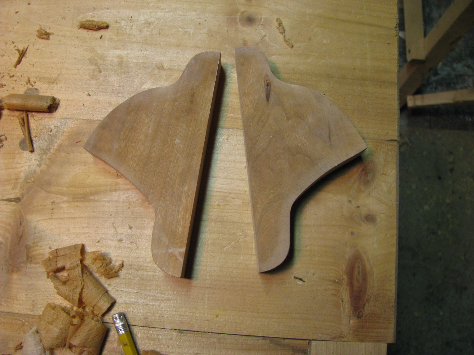
Using the pattern to rough cut the brackets out on the bandsaw.
Using one of the brackets as a pattern for the other.
Double stick tape keeps the brackets together while drilling the holes.
Rough cutting the top of the post, I used a float and my block plane to refine the curve, finishing up with sandpaper.
How it works:
Later I swapped the lower peg for a 3/8" one.
For the pivot, I put it into the drill press and sanded it while it was rotating, creating a nice looking circular pattern on the end. Using a file (with the drill running) I also beveled the edges.
After epoxying the pin into the post, I pinned it with 1/8" brass pin-stock to ensure that it will never fall out, even if the epoxy weakens.
Sanded flush.
Saturday, May 26, 2012
Stand Pivot Design
In order to finalize the design of the pivot I had to first determine what angles I wanted the stand to be able to adjust to. I used a protractor on my own music stand, and determined that one of the positions should be about 20 degrees. The other position should be about 70 degrees for playing above the stand. To design the pivot bracket, I needed to make up a full-size template so I can be sure that the bracket will accommodate the locking pin at the right angle, while also being robust enough. To do this I used sketch-up to print out a full sized template, which I learned to do from this blog article: Printing to Scale in Sketch-up. Then I drew the bracket outline on the printout. Next I will begin the shaping of the bracket.
Zeh, Joe. "Printing to Scale in Sketch-up." Web log post. Chiefwoodworker's Blog. 10 Nov. 2008. Web. 23 May 2012. <http://www.srww.com/blog/?p=117&cpage=1>.
I also did some much needed shop clean-up.
Before:
After:
Zeh, Joe. "Printing to Scale in Sketch-up." Web log post. Chiefwoodworker's Blog. 10 Nov. 2008. Web. 23 May 2012. <http://www.srww.com/blog/?p=117&cpage=1>.
I also did some much needed shop clean-up.
Before:
After:
Sunday, May 13, 2012
Base Joinery
Moving on to the base joinery, which consists of a kind of half-lap joint that I had never cut before. To prepare, I read Tage Frid's primer on mortise and tenon joints, and then I cut a practice joint. It was surprisingly easy.
I find that chalk rubbed in the cut-lines make them more visible on dark walnut.
One down!
Marking out the thickness of the column.
Halfway done.
Unfortunately one of my joints was too tight, and while I was fitting it, it snapped. Luckily it was easily repaired with some glue.
All done.
So far this was one of the most fun parts of the project. Most of the work has been milling, which is slightly boring, so it was nice that I was finally able to do some real joinery. Iwas also very proud of the way it turned out, that (besides the one component breaking) everything went together very smoothly. Overall I am very happy with the base.
Frid, Tage. Tage Frid Teaches Woodworking. Newtown: Taunton, 1986. Print.
I find that chalk rubbed in the cut-lines make them more visible on dark walnut.
One down!
Marking out the thickness of the column.
Halfway done.
Unfortunately one of my joints was too tight, and while I was fitting it, it snapped. Luckily it was easily repaired with some glue.
All done.
So far this was one of the most fun parts of the project. Most of the work has been milling, which is slightly boring, so it was nice that I was finally able to do some real joinery. Iwas also very proud of the way it turned out, that (besides the one component breaking) everything went together very smoothly. Overall I am very happy with the base.
Frid, Tage. Tage Frid Teaches Woodworking. Newtown: Taunton, 1986. Print.
Monday, May 7, 2012
Column Progress
I did some more work this week on the column, mostly planing the outside, and making sure the bottom is square, because that's where the feet attach to. It looks good.
Marking out a square line to plane to (on the left).
Monday, April 30, 2012
Base Milling
Before I can even start working on joinery for the feet, I have to do some milling.
The chalk indicates which surfaces are "reference surfaces", meaning that when I go to mark out joinery, I always reference my square or other layout tool off these surfaces. The face and the edge reference surfaces are perfectly square to each other.
Using the reference edge on the bandsaw fence, all of the parts are ripped to the same width.
The chalk indicates which surfaces are "reference surfaces", meaning that when I go to mark out joinery, I always reference my square or other layout tool off these surfaces. The face and the edge reference surfaces are perfectly square to each other.
Using the reference edge on the bandsaw fence, all of the parts are ripped to the same width.
Friday, April 27, 2012
Central Column Glue-up
Before gluing up the column, I had to make sure that the sliding action was as smooth as possible. With the narrow sides clamped in place, I traced the width of the post onto each side.
Using my bandsaw and jointer plane, I cut and planed the sides to exactly the needed width.
While testing the fit of the post, I aimed for a fit that was fairly snug, as I will later plane the post carefully to make a perfect fit. To begin the glue-up of the column, I begin with gluing one piece on, and wiping away all the glue squeeze-out with a wet rag.
After that was dry, I glued the other side on, using the post as reference, making sure to wipe away any glue squeeze out.
After that was dry I glued on the last piece, making sure to use glue sparingly, as any squeeze out would be essentially impossible to remove.
After all the glue was set, I planed the outside. Not all the joints turned out perfect, but they are passable, after all I knew that this would be the hardest part of the project. Now onto the base.
Using my bandsaw and jointer plane, I cut and planed the sides to exactly the needed width.
While testing the fit of the post, I aimed for a fit that was fairly snug, as I will later plane the post carefully to make a perfect fit. To begin the glue-up of the column, I begin with gluing one piece on, and wiping away all the glue squeeze-out with a wet rag.
After that was dry, I glued the other side on, using the post as reference, making sure to wipe away any glue squeeze out.
After that was dry I glued on the last piece, making sure to use glue sparingly, as any squeeze out would be essentially impossible to remove.
After all the glue was set, I planed the outside. Not all the joints turned out perfect, but they are passable, after all I knew that this would be the hardest part of the project. Now onto the base.
Tuesday, April 17, 2012
Central Post
The main component of the adjustment mechanism is the the central post that slides within the outer column. To get to the thickness needed, I glued up two .75" thick pieces to make a 1.5" square piece.
For the mechanism to be smooth, it is essential to make sure all components are square and consistent thickness, without any twist. Using a square and calipers I made sure the central post is very square and has less than 1/64" change in thickness along its length. The outer column is made of four pieces glued up, so all of those components must be very square and flat as well.
Here is a mock-up of how the sliding mechanism will work:
Testing the squareness and fit for the outer column:
For the mechanism to be smooth, it is essential to make sure all components are square and consistent thickness, without any twist. Using a square and calipers I made sure the central post is very square and has less than 1/64" change in thickness along its length. The outer column is made of four pieces glued up, so all of those components must be very square and flat as well.
Here is a mock-up of how the sliding mechanism will work:
Testing the squareness and fit for the outer column:
Sunday, April 15, 2012
Stand Glue-up
The main focal point of this project is the stand, the part where the music sits. It is also the largest surface, and I chose the most interesting boards for it. First I joint the edges, and then glue them together.
Done properly this kind of joint is stronger than the wood itself.
After the glue is cured, I planed the face to clean up mill marks and to flatten it.

Planing reveals some gum pockets:
After the glue is cured, I planed the face to clean up mill marks and to flatten it.
Planing reveals some gum pockets:
Thursday, April 12, 2012
Planing
After the rough milling, the final step to prepare the wood for joinery is planing all six surfaces. This involves making sure all the edges are square and straight, while at the same time the boards must be planed to the exact width and length needed. Although the boards have already been milled, stress from the drying process causes them to warp, so by the time I use them, they are not flat anymore. To do this I start with my jointer plane, the longest plane I own. The length allows me to flatten the boards, as the bottom rides across the valleys much like how a large ship is better in rough water than a shorter boat. With all the faces squared up, I move on to my smooth plane, which I use to smooth all the surfaces, and make sure they are tear-out free. This is a long process, even with this size of a project. If I was woodworking professionally, I would have to buy an electric planer and jointer which would serve the same purpose, but would allow me to work much faster. Although hand planing is the traditional method, it is very inefficient, and time is money.
This board is bowed:
Saturday, March 31, 2012
Milling
Subscribe to:
Posts (Atom)